The Creo engineering field guide

Creo capabilities.
Develop the whole product.

Shape the concept, define the relationships and prepare the work that follows. Explore the CAD, analysis and production capabilities that fit your engineering responsibilities.

Explore the capabilities
Shape the idea

Shape the concept.
See the possibilities.

Explore form before every detail is fixed. Combine surfaces, existing geometry, 2D layouts and visual communication to establish what the product needs to become. A useful concept also gives the next modeler a clear reference to develop.

Scroll or swipe to explore concept design capabilities.

Surface form

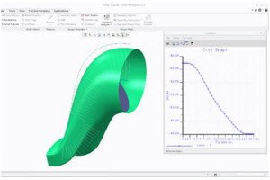
Surface design

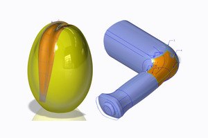
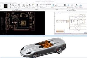
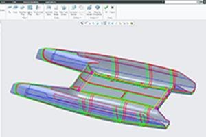
Freeform product surfaces beside a shaped mechanical housing.

Shape freeform geometry around the product’s functional and visual requirements.

For a housing, handle or fairing, consider how visible surfaces meet functional interfaces. Review continuity, access and the intended form before the geometry becomes a detailed production part.

Use in practice

A coherent surface concept for detailed development.

Technical resourceCreo Design EssentialsBrochure · PDF · 6 pages · 32.5 MB
Spatial review

Augmented reality design share

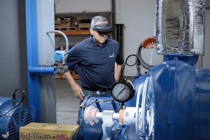
An engineer viewing industrial equipment through an augmented-reality headset.

Share a model in a spatial context for a design discussion.

In a maintenance review, place the model beside the equipment it must clear and check reach and orientation. Choose the model content and viewer access appropriate to the audience and the design discussion.

Use in practice

A spatial review with the clearance or access concern identified.

Technical resourceLink coming soonResource pending
Freeform control

Interactive Surface Design

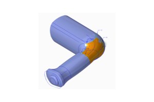
A curved surface connected to mechanical part geometry.

Develop freeform surfaces while retaining relationships to the parametric design.

Use a freeform study when appearance and engineering interfaces need to develop together. Keep the important references understandable so a later dimensional revision can be assessed deliberately.

Use in practice

Freeform geometry connected to the evolving design intent.

Technical resourceInteractive Surface DesignDatasheet · PDF · 3 pages · 0.3 MB
Measured reference

Reverse engineering

Scanned geometry displayed in a reverse-engineering workflow.

Use measured scan geometry as a reference for rebuilding a CAD definition.

Begin with the quality and purpose of the measured data. Identify which surfaces and interfaces must be reconstructed, then compare the developing CAD definition with the available reference.

Use in practice

A reconstructed model with identifiable measurement references.

Technical resourceReverse EngineeringDatasheet · PDF · 3 pages · 0.4 MB
Product imagery

Render Studio

A rendered motor yacht shown in a coastal setting.

Prepare product imagery to communicate form, materials and appearance.

Product imagery can support discussions about finish, proportion and visual direction. Set up the view around the question being reviewed, with materials and lighting appropriate to that discussion.

Use in practice

Product visuals for a focused appearance review.

Technical resourceRender StudioDatasheet · PDF · 2 pages · 0.2 MB
2D concept

Creo Layout

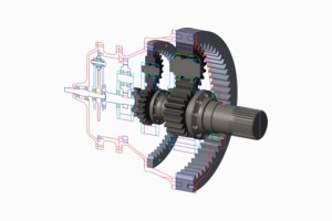
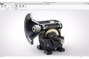
A sectioned mechanical assembly alongside a 2D layout.

Carry useful 2D layout information into the developing 3D design.

Existing layouts often contain useful interface and arrangement decisions. Establish which dimensions and references should guide the 3D model, and keep ownership clear as the detailed design develops.

Use in practice

A layout reference for subsequent 3D development.

Technical resourceLink coming soonResource pending
In your workflow

What needs to be understood before the design becomes a detailed part?

Make intent editable

Model with intent.
Explore design alternatives.

Define the features and relationships that should survive a revision. Use the appropriate modeling method for the material and process, then investigate alternatives or parameter ranges against a stated goal.

Scroll or swipe to explore part modeling capabilities.

Solid bodies

Multibody design

A multibody mechanical-part model displayed on a workstation.

Organize separate solid bodies while developing one part definition.

For a housing, keep the outer form separate from a body used to define the interior cavity until their relationship is ready to review.

Use in practice

A part whose body roles and dependencies are documented for the next revision.

Technical resourceCreo Design EssentialsBrochure · PDF · 6 pages · 32.5 MB
Reusable intent

Design reuse and automation

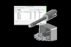
A shaft family table alongside related mechanical components.

Reuse established features, rules and family variations deliberately.

Reuse works best when the original assumptions remain visible. Identify the dimensions, references and permitted variations another engineer should understand before adapting a feature or creating a related part.

Use in practice

A reusable starting point with understood variation boundaries.

Technical resourceCreo Design EssentialsBrochure · PDF · 6 pages · 32.5 MB
Thin-wall geometry

Plastic parts

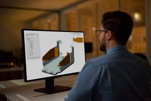
An engineer developing a plastic-part model on a workstation.

Develop thin-wall features and details around the intended molding approach.

An enclosure or molded detail needs geometry that reflects its intended process. Consider wall transitions, interfaces and tooling implications alongside the model, then review the design with manufacturing specialists.

Use in practice

A plastic-part definition prepared for process discussion.

Technical resourceCreo Design EssentialsBrochure · PDF · 6 pages · 32.5 MB
Formed & flat

Sheet metal

An engineer working with sheet-metal geometry in Creo.

Connect formed geometry with the flat-pattern definition needed for production.

A formed component must remain understandable in both its assembled and flattened states. Confirm material, bends and the required manufacturing output while checking how revisions affect neighboring components.

Use in practice

Formed geometry and a reviewed flat-pattern definition.

Technical resourceCreo Design EssentialsBrochure · PDF · 6 pages · 32.5 MB
Parameter goals

Behavioral Modeling

A shaped component beside a parameter-study plot.

Investigate parameter ranges against an explicit engineering goal.

Frame the study around a measurable goal and a defined range of variables. Inspect the assumptions behind a feasible parameter combination before using it to continue the engineering work.

Use in practice

A record of tested parameter ranges and the combinations that meet the stated goal.

Technical resourceBehavioral ModelingDatasheet · PDF · 3 pages · 0.3 MB
Design alternatives

Design exploration

A mechanism assembly with interrelated mechanical components.

Compare alternative modeling directions before choosing the working definition.

Alternative geometry can answer different design questions. Keep each direction traceable to its starting point so the team can compare the relevant differences before choosing a working approach.

Use in practice

Design alternatives with a clear basis for comparison.

Technical resourceDesign ExplorationDatasheet · PDF · 2 pages · 0.2 MB
In your workflow

Which relationships should stay consistent when a dimension or design direction changes?

Build the product relationships

Bring the parts together.
Keep assembly interfaces in view.

A working assembly needs more than a collection of parts. Establish interfaces, references and representation choices so engineers can understand what they own and what a local change may affect.

Scroll or swipe to explore assembly design capabilities.

Component relationships

Assembly modeling

An engineer reviewing an exploded assembly at a workstation.

Build component relationships around the way the product fits together.

A useful assembly explains how components fit, move and depend on one another. Define the interfaces another engineer needs to understand before changing a part or preparing downstream work.

Use in practice

An assembly reference that communicates component relationships.

Technical resourceLink coming soonResource pending
Working display

Assembly management

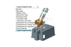
Component-representation choices beside an assembly model.

Choose the representation and display scope appropriate to the current task.

The full product is not always the right working view. Select the representation and component scope for the current task, then test that approach with a representative assembly.

Use in practice

A saved working view that shows the components needed for the review.

Technical resourceCreo Design EssentialsBrochure · PDF · 6 pages · 32.5 MB
Shared references

Advanced assemblies

An engineer reviewing a larger assembly at a workstation.

Coordinate references and structure across a larger assembly.

Larger products distribute design responsibility across people and subassemblies. Establish which references drive interfaces and how a change will be communicated to the engineers developing dependent geometry.

Use in practice

Coordinated assembly references across engineering responsibilities.

Technical resourceAdvanced AssemblyDatasheet · PDF · 3 pages · 9.1 MB
Fabrication detail

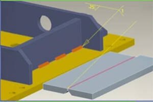
Weld design

Weld annotations on connected mechanical components.

Define weld geometry and the information needed to communicate fabrication.

Fabrication teams need to connect the intended joint with the product geometry. Review the weld definition, surrounding access and required documentation together before handing the work to production.

Use in practice

A weld definition connected to fabrication information.

Technical resourceCreo Design EssentialsBrochure · PDF · 6 pages · 32.5 MB
Assembly sequence

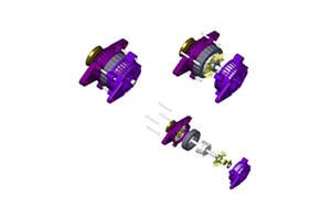
Model animation

Exploded views showing mechanical assembly components.

Explain a mechanism or assembly sequence through a prepared animation.

Use the sequence to show which component must be removed first to reach a fastener. Choose viewpoints and movement that make the engineering discussion easier for the receiving audience.

Use in practice

A service sequence showing access order and the parts involved.

Technical resourceCreo Design EssentialsBrochure · PDF · 6 pages · 32.5 MB
Standard hardware

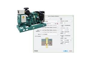
Intelligent fasteners

A fastener-selection dialog beside an industrial assembly model.

Apply standardized hardware selection and placement practices.

Standardized hardware decisions affect interfaces, access and assembly practice. Agree the applicable component library and placement requirements, then review selected fasteners within the surrounding product geometry.

Use in practice

A hardware selection with size, placement and access checks available for review.

Technical resourceIntelligent FastenerDatasheet · PDF · 3 pages · 0.2 MB
In your workflow

Can another engineer identify the interface and continue the work from the assembly reference?

Match the study to the decision

Investigate the behavior.
Inform design with simulation.

Choose the analysis approach for the uncertainty you need to investigate. Interactive feedback can support early geometry changes; deeper studies need suitable materials, loads, restraints, solver scope and engineering review.

Scroll or swipe to explore simulation capabilities.

Core study scope

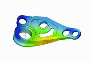
Creo Simulation Elite

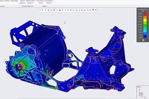
A bracket model with a simulation contour display.

Review the core simulation scope described for the selected Creo environment.

Start with the engineering question and the analysis scope offered in the proposed environment. Confirm the package and extension details before assuming a particular study type is available.

Use in practice

A defined simulation scope for the intended evaluation.

Technical resourceCreo Design EssentialsBrochure · PDF · 6 pages · 32.5 MB
Human interaction

Human factors analysis

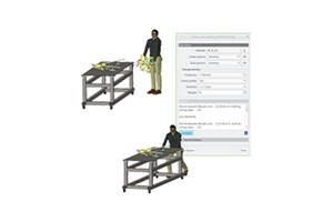
Digital human figures positioned beside a workbench model.

Examine how a person interacts with the intended product or workspace.

Consider the person who will use, reach into or service the product. Define the intended user conditions and assess the interaction within the broader engineering and safety review.

Use in practice

A reviewed product-and-user interaction scenario.

Technical resourceLink coming soonResource pending
Solver-based study

Creo Simulation

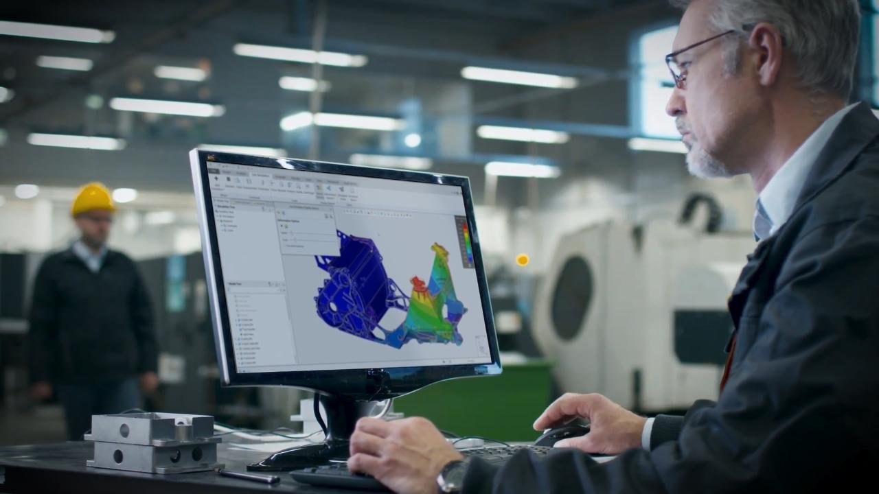
A mechanical assembly with simulation contours displayed in Creo.

Set up structural, thermal or other studies appropriate to the selected solver.

A study needs a defensible model, suitable materials and explicit boundary conditions. Select the relevant analysis capability, then examine whether the setup represents the question the team must answer.

Use in practice

Analysis evidence linked to stated engineering assumptions.

Technical resourceLink coming soonResource pending
Repeated loading

Fatigue analysis

An engineer inspecting an aircraft structure.

Investigate durability under a defined repeated-loading scenario.

Repeated loading introduces a different question from a single load case. Define the loading history and material assumptions, then review the durability study with the responsible engineering specialist.

Use in practice

A durability investigation based on a defined load history.

Technical resourceLink coming soonResource pending
Interactive feedback

Creo Simulation Live

Creo Simulation Live

Use interactive analysis feedback while revising the design.

Compare two rib layouts under the same assumed loads before choosing which one to develop. Keep the setup consistent between alternatives and confirm the study types supported by the selected extension.

Use in practice

Interactive feedback for a scoped design comparison.

Technical resourceLink coming soonResource pending
Specialist analysis

Creo Ansys Simulation

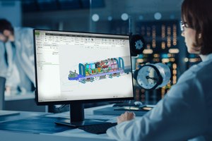
An engineer viewing analysis models and contours on a monitor.

Apply Ansys-powered analysis and meshing to a scoped engineering study.

Use a deeper study when the decision requires the relevant solver and meshing approach. Check model preparation, supported physics and extension scope before interpreting the resulting engineering evidence.

Use in practice

A study record with its mesh, operating conditions and results available for review.

Technical resourceLink coming soonResource pending

Study types depend on the selected solver and extension. Fluid, nonlinear, dynamic or other advanced work needs the relevant scope and a suitable model setup.

In your workflow

What question must the analysis answer, and which assumptions determine the result?

Guidance, context and controlled action

Explore AI assistance.
Keep the task in focus.

Start with the task and the information it needs. General guidance, model-aware assistance and permission-based modifications have different scopes. Confirm the applicable release, entitlement and participation approval before evaluating them.

Scroll or swipe to explore artificial intelligence capabilities.

General guidance

Advise

A Creo model displayed beside an Advise conversation panel.

Find general Creo guidance from supported documentation sources.

Use general guidance to locate a workflow or understand a Creo function. Check the referenced documentation against your release; Advise does not analyze the active model or selections.

Use in practice

A documented next step for a Creo usage question.

Model context

Assist · confirm access

An annotated component model displayed in Creo.

Gather information from supported model context with the required access.

A model-aware question needs the correct assembly, selection and revision in view. Confirm applicable entitlement and participation approval, then review the information returned within the supported design context.

Use in practice

Model-context information for an engineering investigation.

Controlled modifications

Assist automation · limited access

An engine assembly model displayed in Creo.

Review supported changes executed with explicit modification permission.

Permission-based automation applies to supported existing-model operations and remains limited access. Keep modification permission deliberate and review changes; current Assist does not create new features, run analyses or validate physical suitability.

Use in practice

A supported model change reviewed by the responsible user.

Advise does not read the active model. Current Assist automation is a limited-access execution layer with modifications disabled by default; supported work is reviewed by the user. Current Assist does not create new features or models from text, run engineering analyses or validate physical design.

In your workflow

Which context may the assistant use, and who reviews its output?

Connect logic to physical space

Connect electrical design.
Coordinate the mechanical fit.

Electrical connection logic and mechanical packaging must agree. Develop routes in the assembly context, investigate the required separation and prepare information that a harness or routing team can use.

Scroll or swipe to explore electromechanical capabilities.

Physical routing

Piping and cabling design

Routed wiring within a mechanical enclosure.

Route physical connections within the mechanical assembly.

Routes need to satisfy connection logic and the space available in the assembly. Review endpoints, passage, access and the required production information with the people responsible for the system.

Use in practice

A routed model with the connection points and space constraints available for review.

Technical resourcePiping and CablingDatasheet · PDF · 4 pages · 9.5 MB
Electrical separation

Clearance and creepage analysis

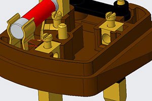
Conductive components and separation geometry within an electrical assembly.

Investigate the required electrical separation between conductive regions.

Electrical separation depends on the geometry and the applicable engineering requirements. Identify the conductive regions and relevant conditions, then use the investigation as part of the electrical design review.

Use in practice

A record of the critical path, its measured distance and the requirement it was checked against.

Technical resourceClearance and CreepageDatasheet · PDF · 2 pages · 0.1 MB
Connection logic

Schematics

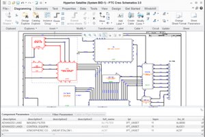
A two-dimensional electrical schematic displayed in Creo.

Define connection logic before developing physical routes.

Identify each endpoint and its source revision so the routing team can trace the connection. Maintain component and connection identity so the electrical logic can be reconciled with the physical assembly.

Use in practice

A connection list with identifiable endpoints for the routing team.

Technical resourceLink coming soonResource pending
Build documentation

Harness modeling and manufacturing

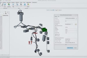
A harness assembly model with component information.

Prepare harness build information from the routed definition.

A routed harness must become information that a build team can use. Agree the required manufacturing documentation, component identification and review points before releasing the harness definition.

Use in practice

Harness build information aligned with the routed product.

Technical resourceHarness ManufacturingDatasheet · PDF · 5 pages · 9.4 MB
In your workflow

Do the connection logic, available space and build definition describe the same product?

Make the requirements usable

Add meaning to the model.
Communicate with precision.

Choose how the receiving team will read the product requirements. Combine model annotations, variation studies and drawing outputs around an identifiable engineering definition, with the relevant standards and review responsibilities.

Scroll or swipe to explore mbd & detailing capabilities.

Product requirements

Model-based definition

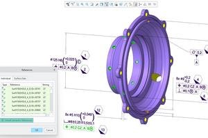
A sectioned model with product-definition annotations.

Place manufacturing requirements with the 3D product definition.

Manufacturing and inspection need an identifiable set of product requirements. Decide which annotations belong with the model and how recipients will access the definition used for their work.

Use in practice

An annotated model with the views and requirements the receiving team needs.

Technical resourceLink coming soonResource pending
Assembly variation

Tolerance analysis

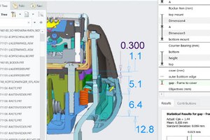
A vehicle model alongside a tolerance-study workspace.

Evaluate a dimension chain and its contribution to assembly variation.

Start with the functional assembly requirement and the dimensions contributing to it. Review the selected dimension chain, variation assumptions and analysis method before accepting a conclusion about the interface.

Use in practice

A tolerance study connected to a functional requirement.

Technical resourceLink coming soonResource pending
Geometric requirements

Geometric dimensioning and tolerancing (GD&T)

GD&T Advisor Advanced

Develop geometric requirements with guided annotation practices.

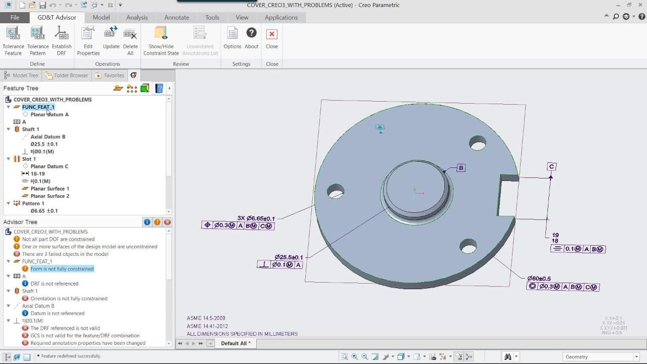
A geometric requirement needs an appropriate reference scheme and a clear purpose. Apply the chosen standard in context, then review how the annotations communicate requirements to manufacturing and inspection.

Use in practice

A reviewed geometric definition for manufacture and inspection.

Technical resourceLink coming soonResource pending
Drawing communication

2D detailing

A detailed component with drawing and annotation information.

Prepare drawing views and details for the receiving team.

Choose the views, sections and notes that make the requirement readable. Check the part reference, revision and intended output format before sharing the drawing with the receiving team.

Use in practice

A readable drawing linked to its engineering reference.

Technical resourceExplore CAD drawing softwareTriStar guide
In your workflow

Which requirements belong in the model, and which outputs must the next team receive?

Prepare the way the part is made

Design for the process.
Prepare for production.

Carry the product model into a specific production method. Machining, additive work, composites and tooling need different preparation, equipment assumptions and checks; select the capabilities around the process you intend to use.

Scroll or swipe to explore manufacturing capabilities.

Build preparation

Additive manufacturing

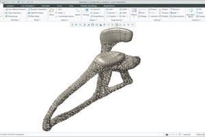
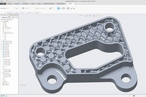
A bracket model containing lattice geometry.

Prepare geometry and build considerations for a selected additive process.

A build approach brings its own material, orientation and equipment considerations. Prepare the geometry for the selected process and review the relevant checks before relying on a production output.

Use in practice

A part prepared for a specified additive workflow.

Technical resourceLink coming soonResource pending
Machining operations

NC Machining

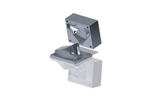
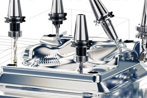
Machining tools arranged around a shaped metal part.

Develop machining operations and toolpaths around the part model.

A machining plan depends on the part, setup, tooling and available equipment. Review access and the intended operations, then verify the resulting preparation within the appropriate manufacturing process.

Use in practice

Machining preparation matched to the part and equipment.

Technical resourceComputer-Aided Manufacturing in CreoBrochure · PDF · 6 pages · 8.3 MB
Production tooling

Tool design

A tooling model with matching production-tool components.

Develop mold and production tooling around the product definition.

Production tooling develops around the product geometry and the intended manufacturing method. Coordinate interfaces, part changes and the information needed by the tooling team as the design progresses.

Use in practice

A tooling model with its parting strategy and product references identified.

Technical resourceComputer-Aided Manufacturing in CreoBrochure · PDF · 6 pages · 8.3 MB
Composite definition

Composites design and manufacturing

A composite structure with layered construction geometry.

Prepare composite structure and the associated manufacturing definition.

Composite structure brings material direction, layered geometry and manufacturing definition together. Keep the intended construction understandable as the part develops, with specialist review of the design and production requirements.

Use in practice

A composite definition prepared for specialist review.

Technical resourceLink coming soonResource pending
Milling strategy

High-speed milling

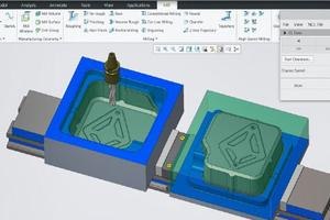
Machining preparation shown around pocket geometry.

Plan milling strategies around the geometry and selected machining capability.

Select the machining strategy around the geometry, tool access and production setup. Confirm the applicable milling capability and equipment assumptions, then review the prepared operation before production use.

Use in practice

A reviewed operation plan with the chosen cutter, access and setup assumptions.

Technical resourceHigh-Speed MillingDatasheet · PDF · 2 pages · 9.2 MB
Forming sequence

Progressive die design

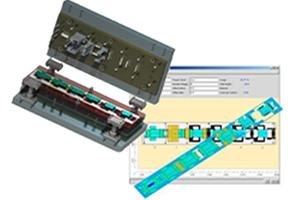
A progressive tooling model alongside successive forming stages.

Develop sequential sheet-metal tooling around the forming process.

A sequence of forming operations must support the intended sheet-metal part. Coordinate the product geometry, operation sequence and tooling references so the manufacturing team can review the proposed approach.

Use in practice

A tooling reference showing which operation forms each feature.

Technical resourceComputer-Aided Manufacturing in CreoBrochure · PDF · 6 pages · 8.3 MB
In your workflow

What must be prepared and verified before the model can support your production process?

Keep the receiving model useful

Cross the CAD boundary.
Keep exchanged data usable.

Treat incoming geometry as an engineering handoff. Confirm the source, supported format and revision, inspect the translated result, and decide how future changes will be managed before relying on it downstream.

Scroll or swipe to explore data exchange capabilities.

External references

Unite Technology

External CAD geometry displayed within a Creo assembly.

Work with supported external CAD geometry in the Creo environment.

Incoming design data needs an agreed source and revision. Confirm the supported application and version combination, then test whether the geometry and required downstream information remain usable.

Use in practice

An assembly that identifies which supplied revision is used and who owns it.

Technical resourceUnite TechnologyDatasheet · PDF · 3 pages · 0.6 MB
Geometry repair

Import DataDoctor

Imported geometry with model-repair information displayed.

Inspect and repair translated geometry before using it downstream.

Translated geometry can require inspection before it supports further design work. Identify gaps or problematic regions, repair the appropriate definition and check the result against the intended engineering use.

Use in practice

Reviewed imported geometry ready for its next task.

Technical resourceLink coming soonResource pending
Source updates

Collaboration extensions

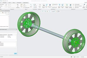
A wheel-and-axle assembly with collaborating CAD references.

Manage supported source references as collaborating designs change.

A supplier or partner update can affect dependent work. Establish how supported source references are maintained, how a changed revision is identified and who reviews its effect on the assembly.

Use in practice

An understood update path for collaborating CAD data.

Technical resourceUnite TechnologyDatasheet · PDF · 3 pages · 0.6 MB
Existing definitions

Legacy data migration

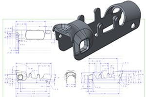
A mechanical bracket model beside its drawing definition.

Plan the transfer and review of existing models and documentation.

A migration should preserve the information the team actually needs. Select representative models and documents, define acceptance checks and plan how the transferred definition will be reviewed before use.

Use in practice

A migration plan with explicit engineering acceptance checks.

Technical resourceCreo Design EssentialsBrochure · PDF · 6 pages · 32.5 MB
Direct edits

Flexible modeling

A component with selected geometry highlighted for direct editing.

Edit suitable geometry directly when preparing or adapting a model.

When an imported housing needs an access opening moved, review the neighboring interfaces affected by the edit. Identify the intended change and inspect how the revised shape affects interfaces, requirements and downstream preparation.

Use in practice

A reviewed geometric adaptation for downstream work.

Technical resourceFlexible ModelingDatasheet · PDF · 2 pages · 0.4 MB

Check supported source applications and versions, translated geometry, required annotations and update behavior with a representative file.

In your workflow

What information must remain usable after the model crosses a CAD boundary?

Support the working environment

Equip the team.
Support the CAD environment.

A capability is useful when the team can deploy, understand and maintain it. Connect environment oversight, skills, calculation context and delivery choices to the work your engineers actually perform.

Scroll or swipe to explore administration capabilities.

Environment oversight

Performance advisor

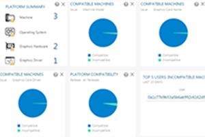
A performance dashboard containing environment and usage information.

Review deployment and environment information to investigate performance.

An environment issue needs evidence from the way Creo is being used. Relate available deployment information to representative models and user tasks before deciding which configuration or support action to investigate.

Use in practice

A performance baseline identifying the affected task, configuration and conditions.

Technical resourceCreo Design EssentialsBrochure · PDF · 6 pages · 32.5 MB
Team knowledge

PTC University

Two engineers discussing work beside a laptop.

Develop the skills needed for the work each engineer owns.

Give a new assembly reviewer a practice model with a known interference and a documented acceptance criterion. Plan time to practice the relevant workflow and agree how the new skill will be applied on a real project.

Use in practice

A learning plan with a representative task each role can complete and demonstrate.

Technical resourceLink coming soonResource pending
Design calculations

Engineering Notebook

An engineer reviewing mechanical design information at a workstation.

Keep calculations and assumptions connected to the model context.

Use a bracket-sizing calculation to show why a thickness was chosen and which assumption would change it. Keep the assumptions, units and design criteria understandable so another person can trace why the value was chosen and review a revision.

Use in practice

Calculation reasoning connected to the CAD design context.

Technical resourceLink coming soonResource pending
Use information

Product insights

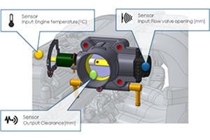
Product-sensor information linked to a model.

Bring relevant product-use information into an engineering investigation.

Product-use information becomes useful when it can be related to an engineering question. Establish the relevant measurements, product reference and review responsibility before using that information to inform a design decision.

Use in practice

A product-feedback question tied to an engineering reference.

Technical resourceLink coming soonResource pending
Cloud delivery

Creo+

A sailing yacht with a connected digital-model visualization.

Compare cloud-enabled delivery, collaboration and administration responsibilities.

A delivery decision affects engineering and IT responsibilities together. Compare collaboration, administration and update practices alongside the modeling scope, then confirm the proposed service boundaries for the team.

Use in practice

A decision record identifying the installation, collaboration and administration responsibilities.

Technical resourceExplore Creo+ servicesTriStar guide
In your workflow

Who owns the environment, the specialist knowledge and the next support decision?

Industry Applications

Engineering needs vary.
Find your industry’s focus.

Build the capability discussion around your product, the people responsible for it and the information the next team needs.

Scroll or swipe to explore all 5 industries. Use Tab to reach each industry link.

Creo Capabilities FAQ

Ask the next question.
Choose Creo with context.

Practical questions about selecting tools, reviewing outputs and planning a Creo environment.

Are all the capabilities shown included in one Creo package?

Capability availability depends on the selected package, extensions, release and environment. Use the technical resources to identify the required scope, then confirm the proposal against your team’s work.

Where should we start when evaluating Creo capabilities?

Choose a representative model and one engineering decision. Identify the person responsible, the inputs they receive and the output the next team needs. Evaluate the relevant capability against that concrete handoff.

How should we choose a simulation approach?

Start with the physical question and required level of evidence. Review the solver’s supported study types, model preparation, boundary conditions and applicable extension. Engineering review and appropriate physical validation remain part of the process.

Can the AI Assistant generate and approve a complete design?

Current Assistant Help lists defined operations and limits. General advice, model interrogation and controlled modifications differ from creating a new model or validating physical suitability. Keep design acceptance with the responsible engineering team.

Will every imported CAD model retain its original intelligence?

Do not assume that every feature, annotation or relationship transfers identically. Check the supported source/version combination and test a representative file, including the downstream information you need to preserve.

How do drawings relate to model-based definition?

They are ways of communicating an engineering definition to its audience. Agree the controlling reference, required annotations and deliverable formats so manufacturing and inspection can use the same requirements.

What should we check in a datasheet or brochure?

Check the named capability, applicable release or extension, supported workflow and any equipment or platform requirements. A capability overview helps frame the discussion; it does not replace a confirmed package and implementation scope.

Is Creo+ a different set of modeling tools?

Creo+ adds a SaaS delivery model and cloud-enabled services around the Creo CAD environment. Compare administration, collaboration and update responsibilities alongside the modeling capabilities your team needs.


Your Creo capability discussion

Bring your design challenge.
Plan your Creo capability scope.

Tell us what you design, what you need to investigate and how the work moves into production.
TriStar can help discuss capabilities, technical resources and a focused evaluation around your team.

Talk to an expert
Start a conversation

Which responsibility
needs deeper tools?

Select a priority to start the conversation.

Choose a priority above.