
Define the connection
Begin with the devices and interfaces the product needs. Agree how identifiers and connection properties will be named so another engineer can follow the design.

Develop the logical definition behind connected products. Bring electrical and fluid-system connections into the design conversation before the team resolves their physical routes.
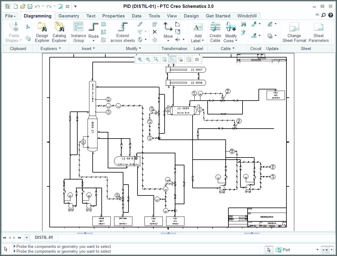
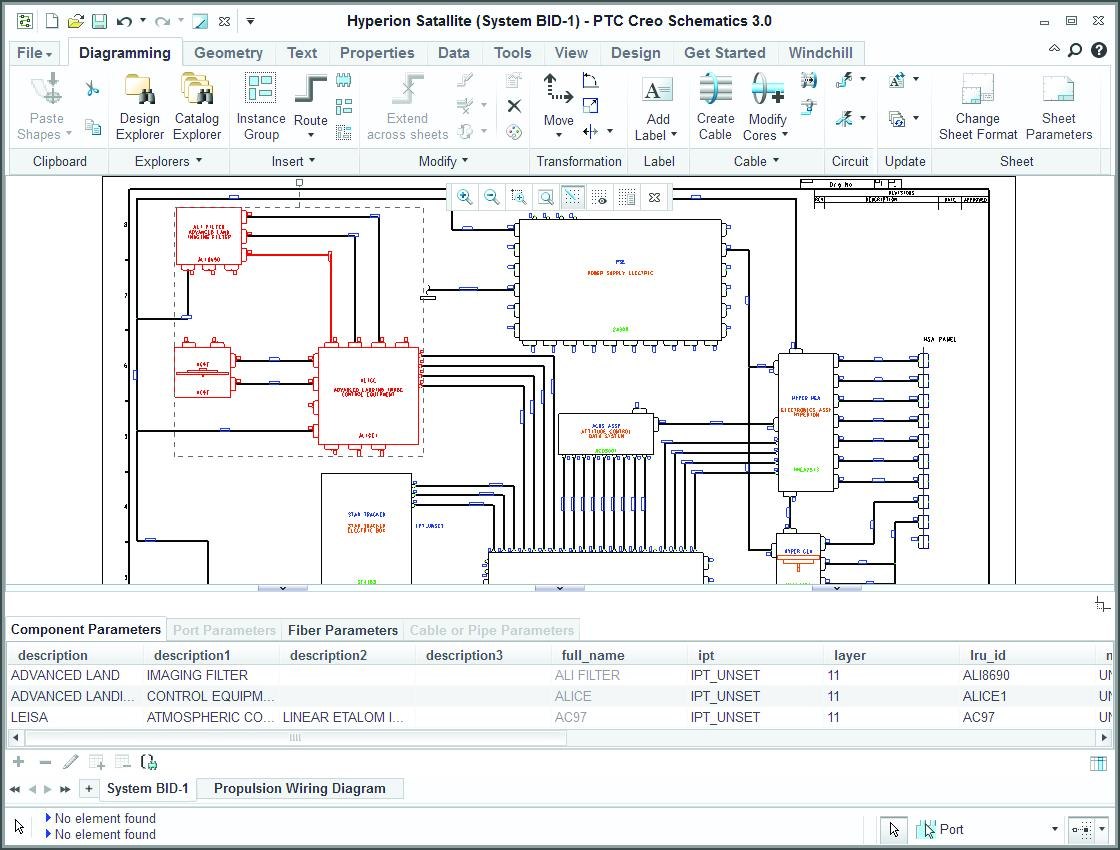
Creo Schematics is a 2D diagramming application for defining connected systems. Electrical and fluid-system diagrams describe components, ports and connections; compatible Creo routing applications can then use that logical information in a 3D assembly.
A schematic answers what connects to what. The assembly answers where those connections can physically go. Review both around the same product: a correct connection list still needs a workable route, and a neat physical route still needs the correct endpoints.
Begin with the devices and interfaces the product needs. Agree how identifiers and connection properties will be named so another engineer can follow the design.
Use the agreed connection information in the applicable 3D routing workflow. Check space, interfaces and the assembly revision together before releasing the result.
Evaluate the connection handoff around a real engineering task. The value is easier to judge when the team can identify which interpretation, prototype or review activity it wants to improve.
Spend less time reinterpreting the drawing.
Sharing schematic connection data with compatible 3D routing tools can reduce manual transcription. Start with one harness or pipe network and examine the handoff before extending the workflow.
Can the receiving designer trace each endpoint back to the agreed source without rebuilding the connection list?
Investigate the system before building it.
Digital definition and analysis can support earlier design comparisons and reduce reliance on physical prototypes. Define the decision to be tested, the necessary tools and the evidence that would justify a change.
Which physical trial could an appropriately reviewed digital study help the team target more precisely?
Check the logical and physical definitions together.
Supported routing workflows can check a routed assembly against its schematic. Keep the model, schematic revision and review ownership aligned; a consistency check is one part of engineering release.
Can the reviewer identify a mismatch, its source revision and the person responsible for resolving it?
These are workflow opportunities, not guaranteed savings. Available checks and analysis depend on the configured products, versions and licenses.
See what Creo Schematics supports from the first diagram to the design review, including which details travel with a connection and which file formats you can use to share it.
A useful starting point is the engineering question, rather than the appearance of the sheet. Agree the symbol conventions and level of detail before establishing the shared library.
Work across sheets, symbols and reusable catalogs.
Establish a consistent starting point for the next design.
For a useful evaluation, bring an existing drawing and a small set of approved symbols. Ask the intended users to find an interface, make a representative edit and explain how that change should be reviewed.
Keep meaningful properties with the connected objects.
Decide which information must travel with each connection.
Separate the identifier used to recognize a component from the properties used to specify it. Check which fields are mandatory, who maintains them and what the receiving workflow needs.
Plan the file handoff and the managed revision.
Treat exchange as a team agreement, not just a file extension.
Test a representative file in the actual receiving environment. Confirm the retained properties, accepted versions and ownership before relying on the exchange for production.
Use connection, inventory and parameter information in review.
Make the review output useful to its recipient.
Agree the report fields, audience and review decision in advance. Confirm current analysis availability and suitability separately; a connection report is not a substitute for validating electrical performance.
Four pages covering diagramming, exchange, catalogs, parameters, reporting and electrical simulation. Published with a 2021 copyright: use it as a scope reference and confirm current release, platform and entitlement details with TriStar.
Download the datasheetCarry the logical definition into a physical routing discussion.
Use these illustrative applications to choose a focused evaluation around your product and its interfaces.
Scroll or swipe to explore all 5 industries. Use Tab to reach each industry link.

Frame a harness or connected subsystem around identifiable interfaces and an agreed configuration. Keep the evaluation within the program’s review and approval process. Schematics in context Can the team trace the proposed connection to its applicable product revision?

Vehicle programs coordinate components across packaging, supplier and manufacturing constraints. Use this setting as a practical example when defining logical connections for electrical and fluid systems. Which product interface and review criteria should guide the evaluation?

Discuss machine wiring, pneumatic controls or a fluid circuit alongside the equipment assembly. Choose a network whose interfaces can be reviewed by both the system designer and the person planning the route. Schematics in context Which machine connection needs a clearer logical-to-physical handoff?

Use an enclosure or equipment interconnect as the discussion point. Identify the connector, signal and mechanical interface information each contributor needs before testing the handoff. Schematics in context Which connector properties must stay consistent across the engineering teams?

Device teams work within defined design controls and documented review responsibilities. Use this setting as a practical example when defining logical connections for electrical and fluid systems. Which product interface and review criteria should guide the evaluation?
Use a representative task to discuss the product scope and the surrounding engineering workflow.
Bring one representative diagram, its component library and the intended receiving assembly. Define a specific handoff to test, then review the required properties, the route and the resulting checks together.
No. Logical diagramming and physical routing have different responsibilities. Confirm the required Creo routing application, extensions, release compatibility and licenses for the proposed environment.
Review naming, required properties, standards and ownership. Have the intended users test a small approved library before expanding it across projects.
Do not assume it will. Use representative files to verify the supported format and version, the transferred values and the receiving application’s interpretation. Keep the source definition available for comparison.
The linked datasheet carries a 2021 copyright. Confirm current platform support, release compatibility, analysis availability and licensing before specifying or purchasing an environment.
Yes. Share your diagramming task, the receiving CAD environment and the review output you need. TriStar can help frame a representative evaluation and clarify the applicable products and requirements.
Tell us which connections you need to define, where the data needs to go and who will review the result.
TriStar can help frame a practical Creo Schematics evaluation around your engineering environment.