Focus the next physical test
Use a virtual mechanism to investigate a question before committing to a prototype. Identify what the digital study can explain and what still needs physical evidence.
A more purposeful test plan.

Examine how a moving assembly responds to its operating conditions. Bring mechanism motion and force analysis into the Creo design workflow, and connect the results to a considered engineering decision.
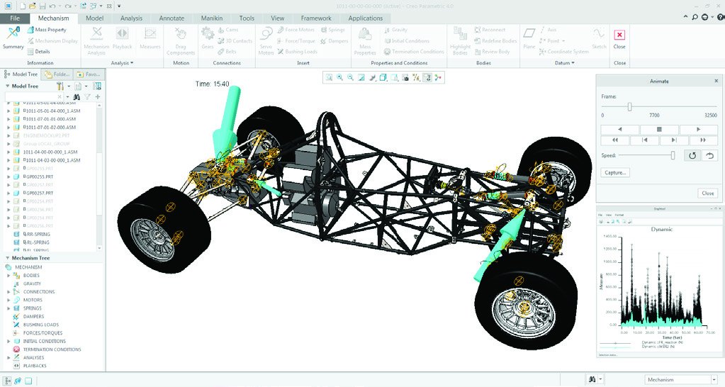
Creo Mechanism Dynamics Option (MDO) is an extension to Creo Parametric for investigating the motion and loading of a mechanism. It supports studies involving effects such as gravity, friction, applied forces, springs and dampers, along with supported gear and belt connections.
Define the mechanism before interpreting the animation. Connections, mass properties, drivers and loads describe how the assembly is expected to behave. A meaningful study ties those definitions to an operating case and to the measurements the engineer needs to review.
The value of a virtual mechanism study is the decision it helps the team make. Define the question, compare the relevant alternatives and retain the assumptions behind the result.
Choose two benefits to explore side by side. Change either selection to consider another priority.
Use a virtual mechanism to investigate a question before committing to a prototype. Identify what the digital study can explain and what still needs physical evidence.
A more purposeful test plan.
Explore a changed connection, driver profile or mechanism arrangement early enough to act on the result. Keep the operating case consistent when comparing alternatives.
A reasoned next design iteration.
Compare alternatives against an agreed motion or loading objective. Record the tradeoffs so the team understands why a promising concept deserves further development.
A visible basis for choosing a direction.
Use motion views, graphs and relevant measures to communicate what the mechanism is doing. Relate the result to the operating scenario rather than presenting an animation without context.
A review that connects movement and evidence.
Work from Creo model data and revisit the study after the design changes. Shared geometry can reduce translation work, but the connections, drivers and loads still need review.
A traceable relationship between model and study.
Identify the relevant reaction or inertial loading for the next engineering task. The datasheet documents transfer to Creo Simulate; confirm the supported handoff for the proposed release and verify the receiving setup.
A clearer handoff to further analysis.
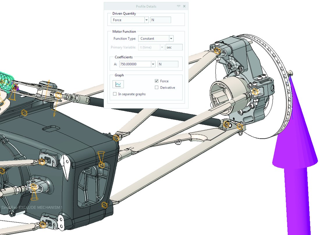
Review kinematic and dynamic studies, measurement outputs, advanced motion behavior and documented integration scope in PTC’s 2018 datasheet.
Confirm current release, platform, license and integration support before using this reference to specify a solution.
Download the MDO datasheetMDO addresses a mechanism question within a broader product-development workflow. Start with the CAD model and the required engineering evidence, then choose the capabilities that support the next task.
Develop the parts and assembly relationships that describe the product, then evaluate the behavior that matters. Keep the mechanism model, its assumptions and the design revision clear as the team moves between design and investigation.
Explore CreoIdentify the moving bodies, connections and operating case that a demonstration should address.
Motion and force results do not by themselves establish stress, fatigue life or compliance. Define the appropriate follow-on study and review.
Connect motion investigation with the rest of the engineering work.
Illustrative applications connect a moving product with an operating case and a responsible engineering review.
Scroll or swipe to explore all 5 industries. Use Tab to reach each industry link.

Frame a component or subsystem mechanism around documented program conditions. Retain configuration, method and review evidence; this example implies no certification or life prediction. Mechanism studies in context What evidence must accompany the motion result?

Vehicle programs coordinate components across packaging, supplier and manufacturing constraints. Use this setting as a practical example when studying mechanism motion, applied loads and dynamic forces. Which product interface and review criteria should guide the evaluation?

Investigate a representative actuator, gear train or handling mechanism. Define the operating case and examine motion and reaction loading before deciding what to change or test. Mechanism studies in context Which connection or operating phase should the study investigate?

Explore a positioning or equipment mechanism where travel and reaction forces influence the design. Review the connections and driver profiles before using the result to guide refinement. Mechanism studies in context Which motion requirement should be assessed first?

Device teams work within defined design controls and documented review responsibilities. Use this setting as a practical example when studying mechanism motion, applied loads and dynamic forces. Which product interface and review criteria should guide the evaluation?
Resolve the setup, evidence and follow-on analysis questions before evaluating a representative assembly.
Kinematic analysis describes position, velocity and acceleration. Dynamic analysis considers forces, torques and effects such as gravity and friction. Choose the study around the question and the evidence needed for the design decision.
Prepare the bodies, connections, mass properties, drivers, loads and operating conditions. Check whether those definitions represent the real mechanism, and identify the measures that the responsible engineer needs to review.
No. An animation helps explain motion, but the model still depends on its assumptions. Review the numerical results and operating cases, and plan appropriate structural analysis or physical verification.
PTC describes those capabilities in the source material. Confirm the exact supported connection types, behavior and required entitlement for the selected Creo release and your proposed mechanism.
The datasheet documents reaction, gravity and inertial-load transfer to Creo Simulate. Confirm the supported workflow and inspect the transferred loads and receiving analysis setup; do not assume every simulation product shares an identical handoff.
Use it to frame a capability discussion and a representative demonstration. Confirm current release, platform, licensing and integration support with TriStar rather than treating the 2018 reference as a current purchase specification.
Tell us what moves, the operating conditions and the decision the result must support.
TriStar can help frame a representative evaluation and clarify the required Creo environment.
