Three-dimensional computer-aided design gives engineers an editable model of a physical product. The model defines the shape of each part and how the parts fit together. That geometry can then support drawings, simulations and manufacturing.
A gearbox shows the connection. The housing locates the shafts, the assembly reveals whether the gears fit, and the release tells the shop what to make and inspect.
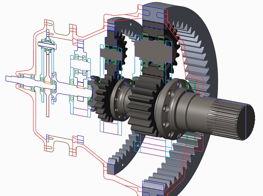
Gearbox assembly shown with its 2D layout geometry in Creo
Define the part
Set the housing’s bearing bores, mounting pattern and wall thickness. Capture the dimensions that need to stay related as the design changes.
Check the assembly
Place the shafts and gears in the housing. Check their fit, bolt access and the space needed to remove a component for service.
Release the design
Use the reviewed model to prepare a drawing or annotated 3D model with the datums and tolerances manufacturing and inspection need.
Why model in 3D
Change the model. See what else changes.
Follow one revision through the work it affects. A larger mounting boss may change part geometry, bolt access, an analysis setup and a released drawing.
Change geometry with intent
Use dimensions and constraints to carry predictable edits through related features. Check regeneration and review the affected views.
Compare concepts sooner
Review alternatives against the same packaging, mass and load assumptions before committing to tooling.
Catch fit problems early
Inspect interference and service clearances in the assembly. Use physical tests where operating conditions or validation requirements call for them.
Make the release easier to use
Give manufacturing, inspection and service teams a consistent reference for the geometry, revision and requirements they need.
PTC’s ZEISS example links model-based product definition with metrology programming. Check which annotations the receiving inspection software can interpret.
Software evaluation
Put 3D CAD tools to the same test.
What to test and record
Model and revise
Change a controlling dimension in a representative assembly. Check which features, interfaces and drawing views update, and record any manual repair.
Exchange and collaborate
Import a supplier model and send a revised file back. Check units, reference stability, version history and who can review or edit the model.
Simulate and release
Run the same fit or performance check in each tool. Review its assumptions, then ask manufacturing and inspection to open the revised drawing or annotated model.
Deploy and support
Have a typical user complete the workflow on the intended hardware. Confirm licensing, required extensions, permissions, training and who handles support.
Compare the evidence from each run. Record which requirements the tool met, which needed a workaround, and what each workaround would cost to support.
Free learning resources
Watch a demo. Try a design change.
Hands-on exercise
One bracket. One revision.
Use one mounting bracket to see whether a change carries from the part to the assembly and drawing. Before starting a trial, check what access you qualify for, how to install it and which tools are included.
01Model the bracket
Constrain the sketch and define the mounting holes. Drive their spacing with a dimension you can change later.
02Revise it in context
Place the bracket in an assembly, change the hole spacing, and check that the mating part still fits and the fasteners have clearance.
03Check the drawing
Regenerate the drawing views. Compare the revised spacing with the model, then check dimensions and notes before sharing.
Creo and Creo+ share the core Creo modeling tools. In either environment, engineers can build parametric parts, assemble them and carry the model into drawings. Check the package and extensions for simulation, manufacturing and other specialized work.
Plan a locally managed desktop rollout. Decide who owns version upgrades, workstation configuration and license access.
Creo delivered as a SaaS subscription with desktop CAD and cloud administration. Check how Control Center fits your deployment, updates and user access.
Design collaboration
Review and exchange models through your established CAD and product data management workflows. Test how revisions reach the people who need them.
Eligible users can work together in real-time collaboration sessions. Test access, how edits are reviewed, and how the result enters your release workflow.
What to test
Run a representative revision from a local workstation through your existing release process.
Invite a second engineer into a session, review a model change together and verify how your team saves the result.
Tools across the workflow
From assembly layout to the shop floor.
Follow a motor bracket from assembly layout to production. Use each capability when the design calls for it. Confirm which tools and extensions your package includes.
Build in context
Assembly modeling
Place a motor and its mounting bracket in the assembly. Check interference, fastener access and whether the motor can be removed for service. Share the agreed mounting interfaces with the team responsible for the enclosure.
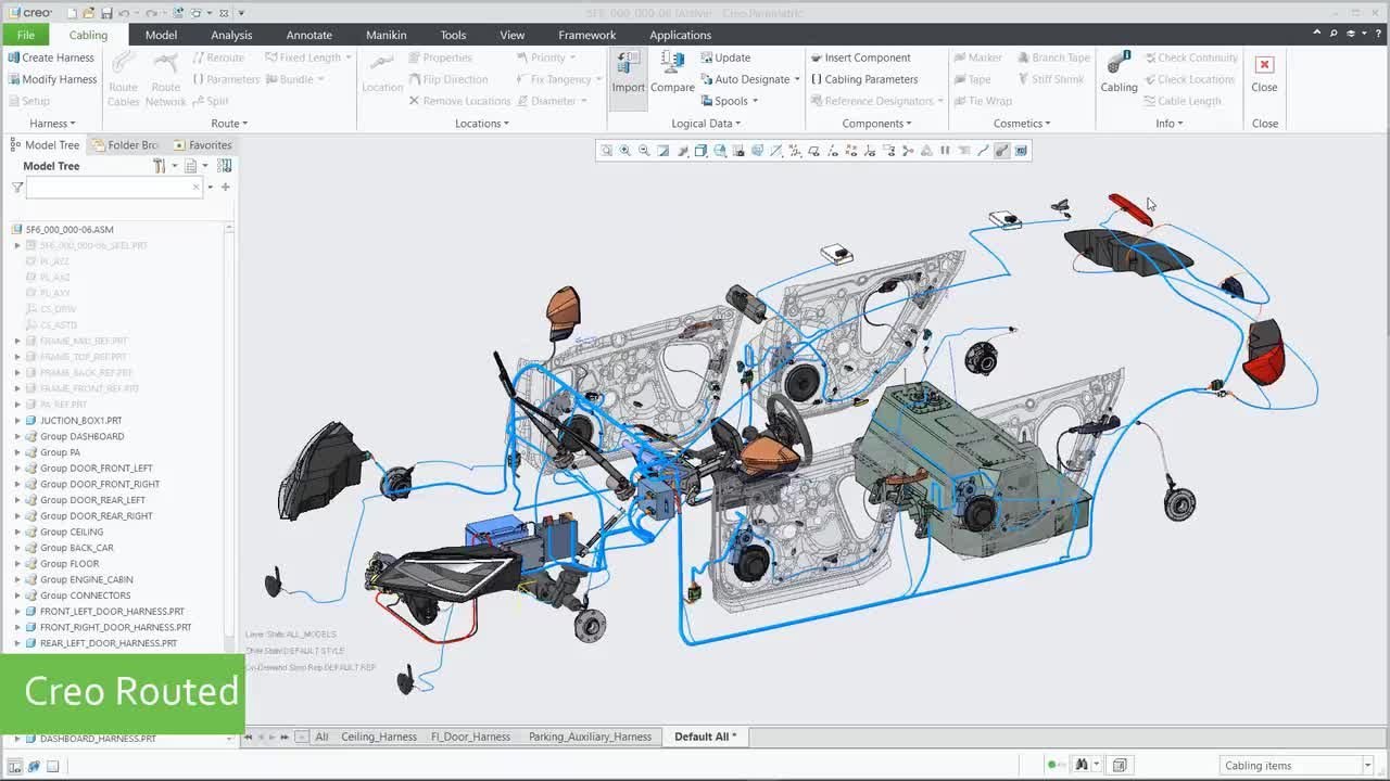
Route the motor harness around moving parts and through the enclosure. Confirm connector locations, bend space and access with the electrical team before issuing the routing definition.
Explore lighter bracket shapes while preserving bolt holes and mounting faces. Compare candidate geometry against the same loads, available space and intended manufacturing process.
Compare bracket deflection under the same loads and restraints. Save the assumptions with the results so reviewers can judge the comparison and identify where physical testing is needed.
Attach datums and tolerances to the bracket model. Ask manufacturing and inspection to verify that their software can read the annotations on the released revision.
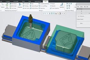
Use the released geometry to plan fixtures, setups and toolpaths. Check tool access and clearances, and review the affected operations when a design revision arrives.
Use 3D CAD to evaluate shape, fit and behavior in context. Use a drawing when a downstream team needs a controlled sheet for manufacturing or inspection. The same model can support both.
How do I get started with 3D CAD?+
Start with a sketch, constrain it, create a solid, then change a key dimension. Add the part to an assembly and make a drawing so you can see how the model supports later work.
Is there a free Creo trial?+
PTC offers Creo evaluation options. Confirm current eligibility, duration, installation requirements and included capabilities before you plan a pilot.
Can 3D CAD replace physical prototyping?+
A model can help eliminate weak options and identify fit or clearance issues earlier. Physical tests remain important where the design needs material, performance or regulatory verification.
Are there Creo certifications?+
PTC offers Creo certification pathways. Confirm the current exam and training requirements for the role you want to develop.
Who uses 3D CAD software?+
Mechanical designers and engineers build models. Manufacturing, inspection and service teams often consume the same geometry and its released definition.
Plan your CAD evaluation
Bring a real design. Make the evaluation count.
Tell TriStar which part, assembly or release workflow you need to test. We can help scope an evaluation around the work your team does.


 Creo