2D CAD Drawing Solutions

Draw with purpose.
Build from a clear plan.

Use 2D CAD to lay out a concept, document how a system connects or communicate exactly what needs to be built.

Explore 2D workflows
Plan
Section
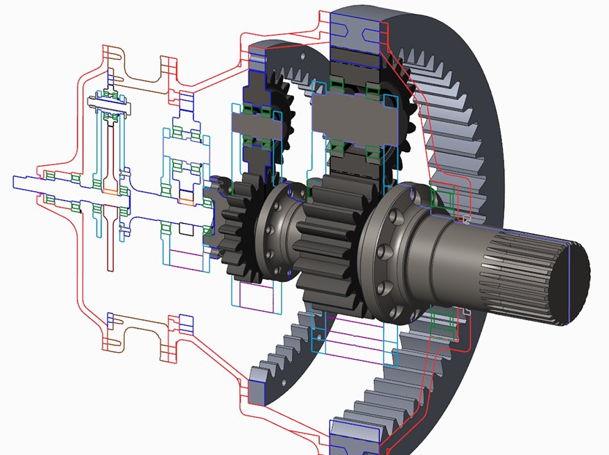
Creo gearbox assembly shown with its 2D layout geometryAssembly · Creo Layout
Plan and section views explain the shaft geometry. The Creo assembly shows how that kind of detail fits into the wider design.
Reading a 2D drawing

What can a 2D CAD
drawing tell you?

2D CAD (computer-aided design) lets engineers and designers create, revise and annotate drawings on a flat plane. They can define geometry at a precise scale and use dimensions, notes and symbols to tell others what to build, install or inspect.

Teams often sketch a layout before building a 3D model, then use drawings to communicate details that need to be read at a glance. The right drawing depends on what the reader needs to know.

Layout
Shows where equipment fits and how much clearance it needs.
Schematic
Shows how devices, wires or pipes connect.
Manufacturing drawing
Defines the dimensions and tolerances a part must meet.
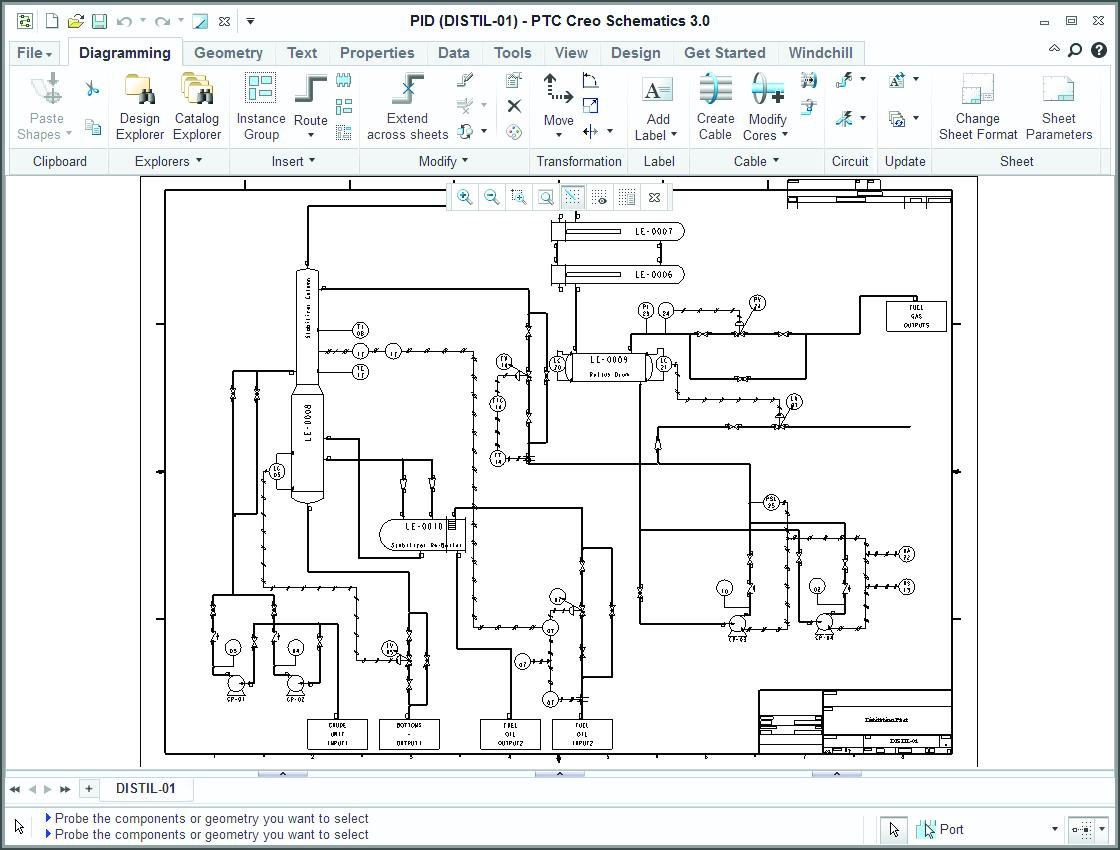
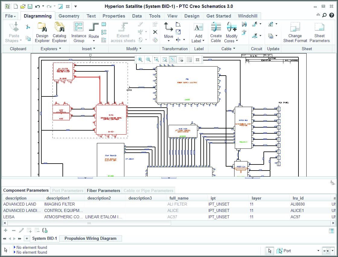
Creo Schematics diagram with symbols and connections
This Creo Schematics drawing shows the connections that guide routing in a 3D assembly.
How 2D CAD is used

From the first sketch
to the shop floor.

Follow a mounting bracket from the first layout to the drawing a machinist and inspector can use.

  1. Lay out the geometry

    For a mounting bracket, set the drawing units and establish a reference edge. Sketch the outline and hole centers on separate layers so you can check the fit against the mating part and revise the layout as needed.

    A concept layout for checking fit.

  2. Add the manufacturing requirements

    Turn the accepted layout into a drawing the shop can use. Specify the hole size and location, add the tolerances that matter for assembly, and use a detail or section view if the main view hides an important feature.

    An annotated drawing for shop and inspection review.

  3. Review and release the drawing

    Walk through the dimensions, notes and revision with manufacturing and inspection. Resolve any questions before issuing the approved sheet in the agreed format. Keep the editable CAD file so later changes can be traced.

    A released sheet and a revision-controlled CAD file.

Drawing and drafting

What makes a drawing
ready to use?

A 2D drawing shows a design from selected viewpoints. Drafting turns those views into a technical document by adding the dimensions, symbols and notes another person needs to build, install or inspect it.

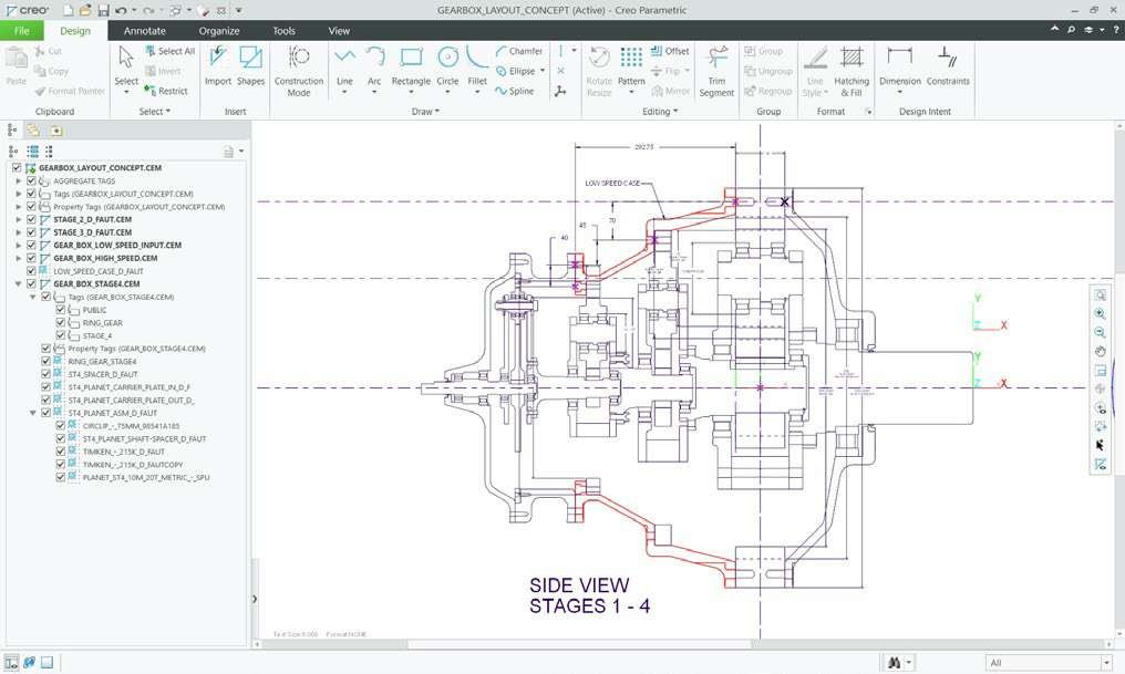
Creo Layout showing a side view of a multistage gearbox with dimensions and dashed shaft centerlines.
Gearbox layout in CreoSide view · Stages 1–4

How to read this drawing

  1. Dimensions

    The dimension line above the gearbox spans two reference points. On a production drawing, the value and any applicable tolerance tell the shop what to make and inspection what to check.

  2. Centerlines

    The dashed line through the shaft identifies its axis. Centerlines help readers align features across views and distinguish reference geometry from physical edges.

  3. View labels

    The side-view label tells readers how the gearbox is oriented. Add a section view to reveal an internal bore or an enlarged detail when a small feature is hard to read.

An engineer reviews an exploded product model at a CAD workstation.
Why teams use 2D CAD

Revise faster.
Keep the details clear.

A well-structured drawing helps teams find the right information, revise it efficiently and agree on what has to be built.

Keep drawing sets organized

Separate geometry, dimensions and reference information with layers. Use approved title blocks, symbols and templates so related sheets have a consistent structure.

On a plant layout, show equipment footprints and access clearances together for review, then hide the reference layers when preparing the installation sheet.

Revise drawings faster

Edit existing geometry and reuse standard details when a design changes. Keep the editable drawing with its revision history, and review every affected view before sharing an update.

If a machine guard changes, revise its mounting detail and check the related sheets before sending the new revision to fabrication.

Communicate requirements precisely

Draw at a defined scale and use dimensions, tolerances and notes to state what the reader needs to verify. A shared drawing gives design, manufacturing and inspection a common reference.

For a machined plate, state the hole size and location on the drawing so the shop and inspector can use the same requirements.

What you can design

Draw the part.
Map the system.

Explore three ways teams use 2D CAD to communicate what to build, connect or service.

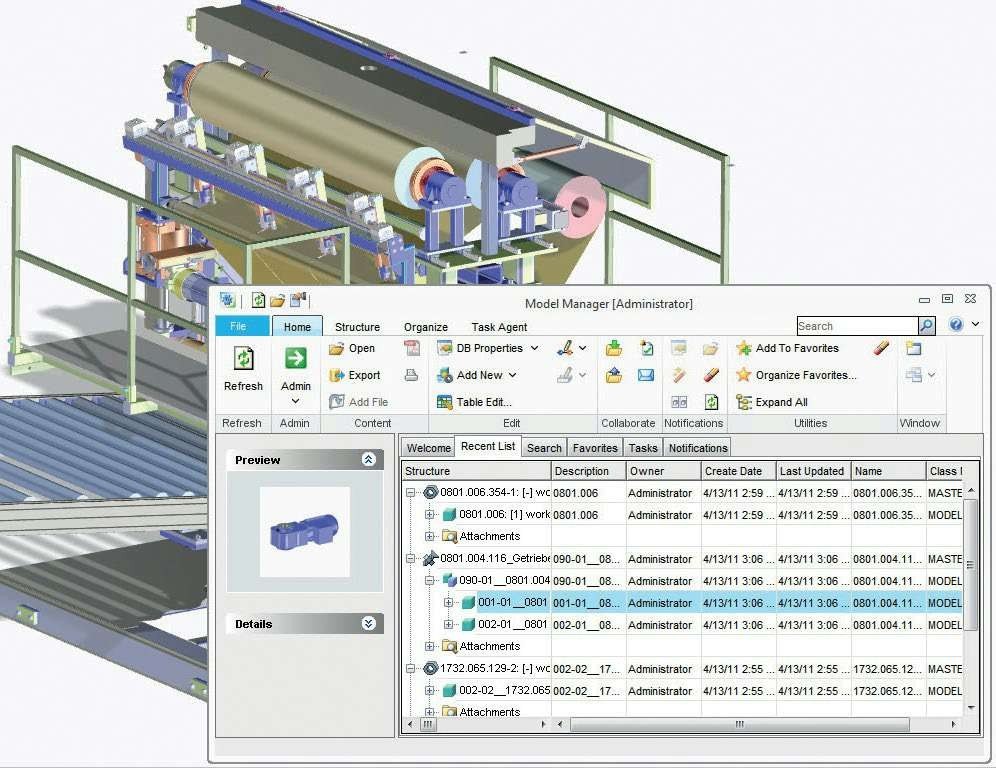
Mechanical assembly displayed in Creo Elements/Direct
Mechanical assembly in Creo Elements/Direct

Make a part the shop can inspect

A roller assembly drawing can use a front view to locate the supports and a section view to show how a shaft seats in its bearing. Dimensions and tolerances give machining and inspection the same requirements to work from.

Typical deliverable
A part drawing with orthographic views, sections and tolerances.
Connection properties displayed in the Creo Schematics interface
Connection properties in Creo Schematics

Show how components connect

An electrical schematic can trace a motor circuit from its power source to its terminals. A fluid schematic can show the equivalent paths through valves and actuators. Reference labels let technicians follow connections across sheets and cross-check them against the physical installation.

Typical deliverable
A wiring or fluid schematic with connection and component identifiers.
Gearbox layout geometry beside its modeled gearing in Creo Layout
Layout geometry and modeled gearbox in Creo

Plan the envelope and service access

A concept layout can set the footprint of a gearbox and reserve room for mounting and service access before the assembly is modeled. After the design is defined, an exploded technical illustration can show which parts to remove and in what order.

Typical deliverable
A concept layout for design review or an illustrated procedure for service.
Key drafting capabilities

The tools behind
a precise drawing.

Different tools help teams define geometry, document how a system works and carry design information into manufacturing or service.

Geometry and constraints
Use snaps and construction lines to place geometry precisely. In Creo Layout, constraints can hold critical relationships as dimensions change. Creo Elements/Direct supports direct edits when you need to adjust existing geometry without rebuilding a feature history.
Layers and schematic symbols
Use layers to separate reference geometry from what belongs on the issued sheet. In Creo Schematics, use reusable symbols and connection identifiers to document electrical, piping or HVAC systems and support compatible 3D routing workflows.
Drawing views and annotations
In Creo Parametric, generate drawing views from a 3D model, then add the dimensions and notes the shop needs. Use section and detail views to reveal features that the main view cannot show clearly. Review the drawing again after a model change.
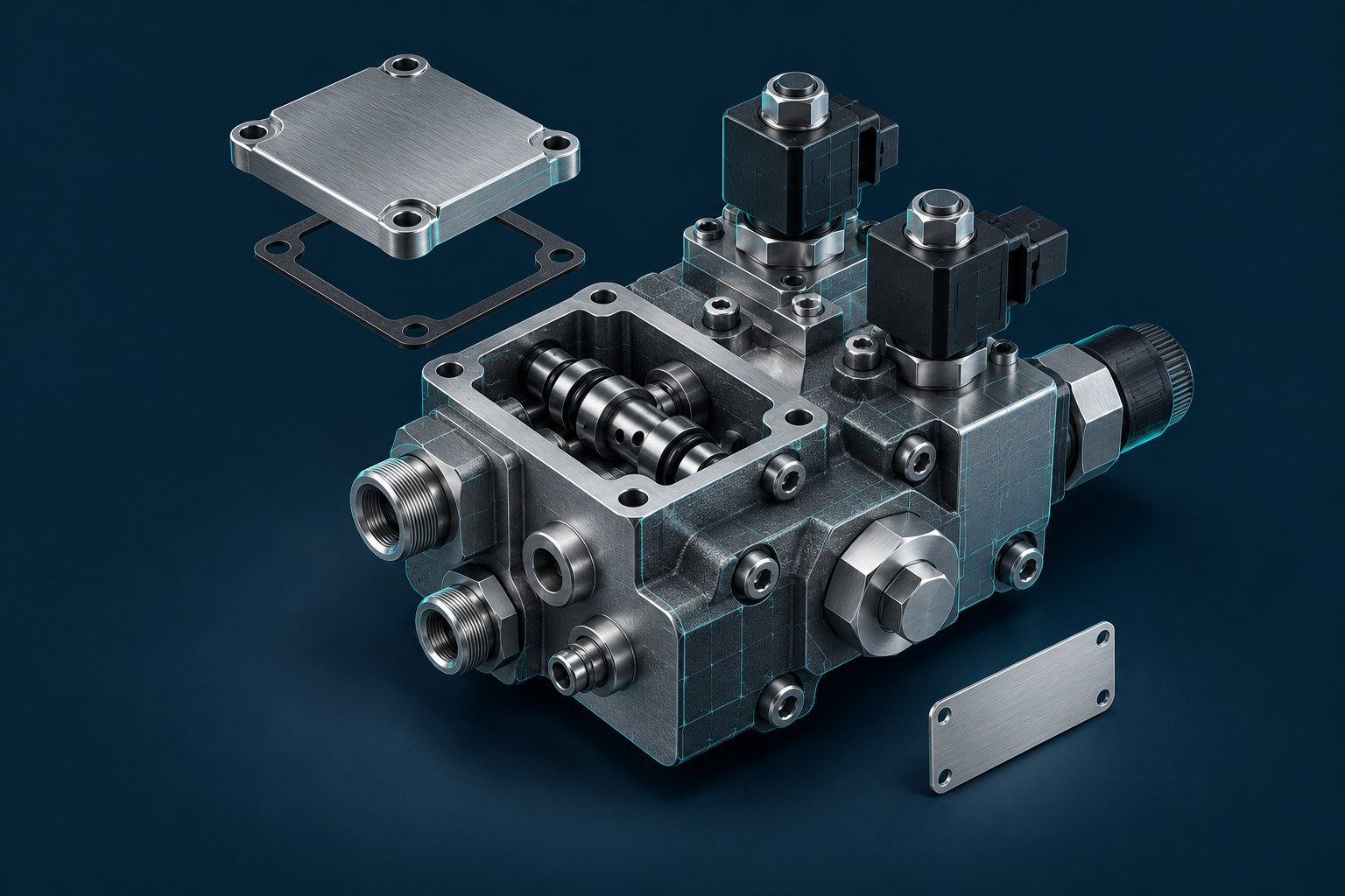
Exploded view of a valve assembly with the cover and gasket separated from the body.

Reuse CAD data for service

PTC Illustrate can reuse a 3D model to create exploded views, parts callouts and step-by-step instructions. The separated cover and gasket show how an illustration can make a service task easier to follow.

2D CAD software

Choose the right tool
for the drawing.

Start with the deliverable you need, then compare the tools for creating, revising and sharing it.

Creo Parametric

Generate drawing views from the model and annotate them for manufacturing and inspection.

Explore Creo ↗

PTC Illustrate

Reuse CAD geometry for exploded views, part callouts and step-by-step service illustrations.

Explore Arbortext ↗
Working across 2D and 3D

From a 2D layout
to a 3D assembly.

A gearbox layout establishes where the shafts, housing and mounting points belong. In Creo Parametric, selected layout geometry can guide the assembly while engineers check how the parts fit and whether there is room to install or service them.

Gearbox side layout in Creo with shaft centerlines and housing geometry.

Set the geometry in 2D

Agree on shaft centerlines, the housing envelope and mounting interfaces. Use the layout to record relationships that need to carry into the assembly.

Modeled gearbox shafts and gears beside their 2D Creo layout geometry.

Check the assembly in 3D

Reference selected layout geometry as you build the parts. Check the space around the gears and shafts, and confirm there is room to remove components during service.

What the assembly helps you deliver

Production drawing
Generate views from the model, then add the dimensions, tolerances and notes manufacturing needs. After a model change, check the views and annotations before releasing a revision.
Service illustration
Use the assembly configuration that matches the equipment in the field. Create an exploded view to identify replaceable parts and show the order of removal.
Watch a 2D layout guide a 3D model
PTC demonstrates the layout-to-model workflow in Creo 2.0. Watch on YouTube ↗
Industry applications

Where 2D drawings
go to work.

Start with what the people building, installing or servicing the product need to see.

Industrial machinery and mechanical assemblies.

Industrial Machinery

Machine layouts
Show machine footprints and service clearances, then issue installation drawings for the field.

Where does the maintenance team need access?

Explore Industrial Machinery
Precision equipment for electronic-component manufacturing.

Electronics & High-Tech

Electronics integration
Document connector openings and mounting interfaces alongside the wiring logic.

Which interfaces must both disciplines agree on?

Explore Electronics & High-Tech
Jet engine in an aerospace manufacturing facility.

Aerospace & Defense

Configuration-specific drawings
Document equipment interfaces and installation details within the project’s configuration and release practices.

Which configuration and revision should the receiving team use?

Explore Aerospace & Defense
FAQ

Before you start
your next drawing.

Check what to draft in 2D, what to carry into 3D, and what to review when the model changes.

When is 2D CAD the better starting point?

Start in 2D for flat layouts, circuit logic and manufacturing sheets. Use 3D when you need to study fit, clearance or how parts interact through space.

What is an isometric drawing?

An isometric view shows three sides of a part in one image. It helps readers visualize the part, while orthographic and section views usually carry the detailed requirements.

Can I reuse legacy DWG or DXF drawings?

Many tools can import these formats. Check the units, scale, fonts, layers and any geometry you intend to reuse before migrating a library.

Will a drawing update when its model changes?

Associative views can reflect changes in their referenced model. Review affected dimensions, notes and views before releasing a new revision.

Plan your drafting workflow

What are you drafting next?
Talk it through with TriStar.

Tell TriStar what you draw, what your team needs to share and which tools you already use.

Talk to an expert
Start a conversation

What do you
need to produce?

Select a priority to start the conversation.

Choose a priority above.