
Computer-aided design / From idea to engineering definition

Design intent.
Built into
every detail.

Shape the product, investigate its behavior, and prepare the definition others will build from. Bring modeling, simulation, drawings, and manufacturing preparation into a CAD workflow that can carry the next design change.

Explore CAD capabilities
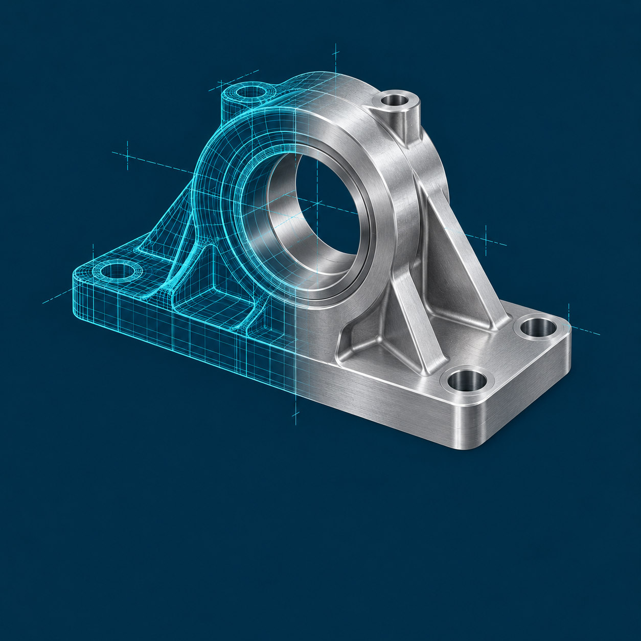
Parametric bearing support transitioning from cyan CAD wireframe geometry to a shaded machined aluminum model
FEATURES · RELATIONSHIPS · DEFINITIONA part of something bigger.
The relationship behind the geometry

A dimension changes.
The intent remains.

The model should know which relationships matter. A mounting pattern stays centered. A bore remains concentric. A feature follows its reference when an interface changes.

A useful model makes those choices understandable to the next engineer. References, constraints and reusable features give design changes a consistent starting point.

EXPLORE A SIMPLE RELATIONSHIP

Change the plate width. The mounting holes keep the same edge offsets, and the spacing updates with the geometry.

PARAMETRIC STUDY / MOUNTING INTERFACEMODEL A
Parametric mounting plateA mounting plate with a width of 300 millimeters, a height of 140 millimeters, and two 20 millimeter mounting holes. Each hole center stays 25 millimeters from its side edge.300 mm140Hole spacing 250 mm25SYMMETRIC ABOUT CENTER
PLATE WIDTH
300 mm width · 250 mm hole spacing25 mm edge offsets retained. Hole diameter and plate height unchanged.
The capabilities within CAD

More than a model.
A working engineering foundation.

Start with the engineering task. Explore the features that shape the geometry, inform a design decision, and carry the definition into production.

Shape the product.

Develop the form and the relationships behind it. Coordinate individual parts, complete assemblies and the geometry your partners supply.

  • Concept & surface design

    Explore a product’s proportions and surface character before every detail is settled. Develop curves, freeform shapes and controlled surfaces around the space and experience the product needs.

    In practice

    Refine an enclosure, grip or fairing while checking its transitions and relationship to the components inside.

    You build

    A developed form ready for detailed engineering.

    Explore concept & surface design
  • Parametric 3D design

    Build parts with dimensions, constraints and feature relationships that capture why the geometry exists. Reusable features and controlled variants carry engineering knowledge into the next design.

    In practice

    Change a mounting plate’s width while retaining its hole sizes, edge offsets and deliberate reference relationships.

    You build

    Editable part geometry with understandable design intent.

    Explore 3D CAD software
  • Assembly design

    Develop a component in the context of the product around it. Organize assemblies, coordinate interfaces and examine fit, clearance and motion as the design grows.

    In practice

    Review a revised motor mount against the housing, shaft, fasteners and space needed for assembly.

    You build

    Coordinated components, interfaces and assembly relationships.

    Explore assembly design
  • MultiCAD collaboration

    Bring supplier and customer geometry into the product context. Plan how supported non-native models are referenced, exchanged and updated, with ownership and revision responsibilities made clear.

    In practice

    Review a supplier gearbox’s mounting interface and assess a later update without assuming its original feature history transfers.

    You build

    A defined exchange and update workflow for partner geometry.

    Explore MultiCAD collaboration

Improve the design.

Bring performance questions into CAD while the geometry can still change. Compare alternatives against explicit conditions and retain the reasoning behind the choice.

  • Simulation & analysis

    Investigate product behavior as part of design development. Use suitable structural, thermal, modal or fluid studies to compare geometry and materials under stated loads and operating conditions.

    In practice

    Compare housing ribs under the same restraints, then review the assumptions and results before revising the model.

    You build

    Design feedback and reviewable analysis evidence.

    Explore CAD simulation & analysis
  • Generative design

    Explore candidate geometry from defined objectives, loads, constraints and manufacturing considerations. Give the engineering team another way to investigate how a part could meet its intended task.

    In practice

    Explore a lighter bracket while preserving attachment regions and reviewing the proposed geometry for the intended process.

    You build

    Candidate designs for engineering evaluation and refinement.

    Explore AI & generative design

Define it for production.

Make the design useful to manufacturing and inspection. Connect its geometry to the information, processes and material decisions needed to prepare the work.

  • Drawings & model-based definition

    Communicate dimensions, geometric tolerances, datums and manufacturing requirements through associative drawings or information attached to the 3D model. Choose the definition each downstream team can use.

    In practice

    Keep hole requirements and datum references with the geometry used in a manufacturing or inspection review.

    You build

    Drawings or an annotated model with product requirements.

    Explore CAD drawing software
  • CAD/CAM & tooling

    Prepare machining and tooling around the part definition. Develop operations, toolpaths and related manufacturing geometry, then examine how a design revision affects the preparation already in place.

    In practice

    Revise a machined pocket, update its associated manufacturing model and review the affected operations before release.

    You build

    Manufacturing preparation connected to the design geometry.

    Explore CAD/CAM & tooling
  • Additive manufacturing

    Design around the opportunities and limits of a selected additive process. Explore part consolidation, lattice structures and build preparation while accounting for the material, machine and required finishing work.

    In practice

    Reconsider a multi-part bracket as a printable design, then assess its build and post-processing requirements.

    You build

    Geometry and build preparation for an evaluated additive process.

    Explore additive manufacturing
  • Composite design & manufacturing

    Develop composite parts around their material architecture as well as their external shape. Define plies and layup information, and connect those design decisions to manufacturing preparation.

    In practice

    Review a panel’s ply boundaries, orientations and layup sequence alongside the tooling and product geometry.

    You build

    Composite geometry, ply definitions and layup context.

    Explore composite design

Available functions, analysis depth, supported data and manufacturing methods depend on the selected CAD product, package and extensions.

The design belongs to a bigger thread

Keep the reasoning.
Carry the design forward.

Follow the same engine assembly from engineering assumptions into CAD and its product record. Within CAD, change the perspective to see how modeling, analysis and clear product visuals inform the work.

Engineering calculations Mathcad

Establish the conditions.

Document loads, assumptions, units and equations. Carry the selected parameters into design with a sizing method another engineer can follow.

  • Loads & units
  • Materials & limits
  • Sizing assumptions
CAD Creo / CAD workflow

Develop the definition.

Explore within CAD

Build the relationships.

Dimensions and references connect cylinder spacing, shaft alignment and mounting interfaces. Preserve those relationships as the design changes.

Let the evidence inform the design.

Review loads, restraints and material assumptions, then use suitable simulation to compare behavior. Feed the engineering findings back into the CAD definition.

Make the design easier to understand.

Carry the same geometry into product visualization. Use materials, lighting and camera views to communicate form, finishes and assembly intent in a design review.

PLM Windchill

Control the definition.

Manage CAD documents, product structures, revisions and change context. Keep the design and its supporting records available for review and controlled downstream use.

  • CAD definition
  • Supporting evidence
  • Revision context
CAD software & companion tools

Your CAD environment.
Built around the work.

Design the product. Communicate the result. Reuse what works. Combine the CAD environment and specialist tools that fit your engineering workflow.

Design & engineer

Creo

Build parametric parts, assemblies, and manufacturing definitions. Connect design intent with analysis, drawings, model-based definition, and production preparation.

Explore Creo
Collaborate & administer

Creo+

Choose SaaS delivery of the Creo design environment, with cloud collaboration and centralized administration. Evaluate the deployment around your team and existing models.

Compare Creo & Creo+
Render & communicate

KeyShot Studio

Turn CAD geometry into photorealistic images and animations. Explore materials, finishes, lighting, and camera views for design reviews and product communication.

Explore KeyShot
Discover & reuse

MAIT ModelSearch

Find similar or identical 3D parts by geometry. Discover reusable models in supported Windchill or Model Manager environments before creating another part.

Explore ModelSearch

TriStar helps match the tools, integrations, and training to your models and team. Companion products are selected separately; compatibility and licensing depend on your environment.

Explore all technologies
Questions worth asking

Clarity before
the next change.

Start with the design process, then evaluate the tools in that context.

How do we choose the right analysis or manufacturing capabilities?

Start with the engineering question, required evidence and intended production process. Early design feedback, detailed structural or fluid analysis, CAM, additive and composites address different tasks. Available functions depend on the selected CAD product, package and extensions; evaluate representative models and conditions before choosing a configuration.

Do we need to replace drawings with model-based definition?

Drawings and MBD can coexist. Begin with the information manufacturing, quality, suppliers and service actually need. An MBD approach requires suitable authoring practices, compatible downstream tools and control of the released definition as well as 3D annotations.

What should we check before connecting visualization or part-reuse tools?

Check the CAD version, supported plugin, data environment and update behavior. A visualization connection should preserve the intended scene as geometry changes; a part-reuse tool must support the system that manages your models. Evaluate a representative model and revision cycle. Companion products, compatibility and integrations are selected and scoped separately.

How are Creo and Creo+ different?

Creo provides the CAD design environment and a range of engineering capabilities. Creo+ delivers Creo through a SaaS subscription with cloud services for collaboration and administration. It retains the Creo design environment and is distinct from Onshape’s browser-based, cloud-native CAD and built-in PDM.

Your next design advantage

Let’s build on
your design intent.

Bring us the assembly, revision, or manufacturing handoff that needs a better way forward.
We’ll help shape a CAD workflow around the products you build and the people who build them.

Talk to an expert
Start a conversation

What would you
like to connect?

Select a priority to start the conversation.

Choose a priority above.